The engine of the Space Shuttle
The Aerojet Rocketdyne RS-25 was the Space Shuttle Main Engine (SSME), it is a liquid-fuel cryogenic rocket engine used on NASA's Space Shuttle and is currently used on the Space Launch System (SLS).

Designed and manufactured in the United States by Rocketdyne (later Pratt & Whitney Rocketdyne and Aerojet Rocketdyne), the RS-25 burns cryogenic liquid hydrogen and liquid oxygen propellants, with each engine producing 1,859 kN thrust at liftoff. Although RS-25's heritage traces back to the 1960s, its concerted development began in the 1970s with the first flight, STS-1, on April 12, 1981. The RS-25 has undergone upgrades over its operational history to improve the engine's reliability, safety, and maintenance load.
 The engine produces a specific impulse (Isp) of 452 seconds (4.43 kN-sec/kg) in a vacuum, or 366 seconds (3.59 kN-sec/kg) at sea level, has a mass of approximately 3.5 tonnes (7,700 pounds) and is capable of throttling between 67% and 109% of its rated power level in one-percent increments. Components of the RS-25 operate at temperatures ranging from −253 to 3,300 °C.
The Space Shuttle used a cluster of three RS-25 engines mounted at the stern of the orbiter, with fuel drawn from the external tank. The engines were used for propulsion throughout the spacecraft ascent, with total thrust increased by two solid rocket boosters and the orbiter's two AJ10 orbital maneuvering system engines. Following each flight, the RS-25 engines were removed from the orbiter, inspected, refurbished, and reused on another mission. On Space Launch System flights, the engines are expended. For the first four flights, machines left over from the Space Shuttle program will be refurbished and used before NASA switches to the simplified RS-25E variant.
How rocket engines work
The amount of thrust produced by the rocket depends on the mass flow rate through the engine, the exit velocity of the exhaust, and the pressure at the nozzle exit. All of these variables depend on the design of the nozzle. The smallest cross-sectional area of the nozzle is called the throat of the nozzle. The hot exhaust flow is choked at the throat, which means that the Mach number is equal to 1.0 in the throat and the mass flow rate m dot is determined by the throat area. The area ratio from the throat to the exit Ae sets the exit velocity Ve and the exit pressure pe. You can explore the design and operation of a rocket nozzle with our interactive nozzle simulator program which runs on your browser.
The exit pressure is only equal to free stream pressure at some design conditions. We must, therefore, use the more extended version of the generalized thrust equation to describe the thrust of the system. If the free stream pressure is given by p0, the thrust F equation becomes:
F = m dot * Ve + (pe - p0) * Ae
Notice that there is no free stream mass times free stream velocity term in the thrust equation because no external air is brought on board. Since the oxidizer is carried on board the rocket, rockets can generate thrust in a vacuum where there is no other source of oxygen. That's why a rocket will work in space, where there is no surrounding air, and a gas turbine or propeller will not work. Turbine engines and propellers rely on the atmosphere to provide air as the working fluid for propulsion and oxygen in the air as an oxidizer for combustion.
The thrust equation is shown above works for both liquid and solid rocket engines. There is also an efficiency parameter called the specific impulse which works for both types of rockets and greatly simplifies the performance analysis for rockets.
The details of how to mix and burn the fuel and oxidizer, without blowing out the flame, are very complex. It DOES take a rocket scientist to figure it out!
So simply the fuel and oxidizer burn in the combustion chamber and the high-pressure hot gasses have to go thru a small hole into a larger diameter nozzle to create thrust which makes the thing fly.
But these parts have to be cooled.
In the modern age, it's a simple task because of our advanced manufacturing processes like 3d printing but in the 70s it was a much more significant challenge to manufacture cooling channels inside the nozzle.
How it was manufactured
In order to can be reused it cant be made out of tubing, and it also has to withstand the huge forces during and after launch.
In this modern era, We would simply 3d print it. But in the 1970s it was not possible.
Because of the huge size its have to be cast.
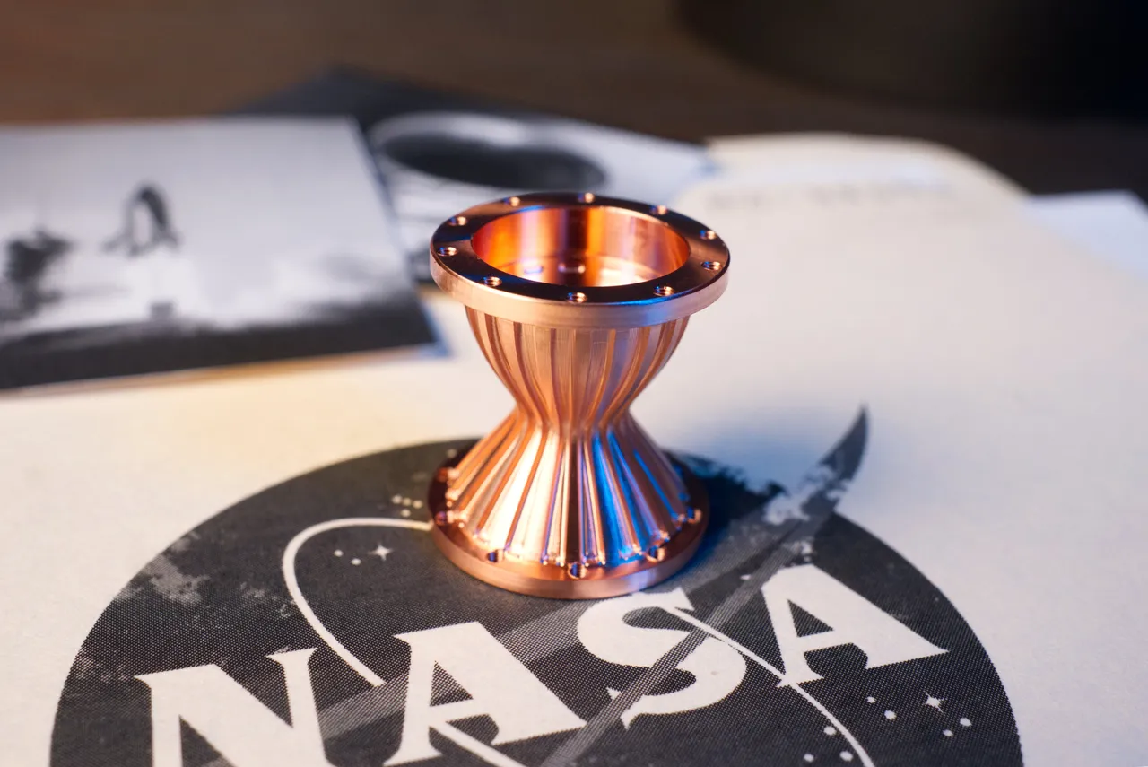
After the casting process engineer has to cover the cooling channels with a mix of wax and graphite and then rub down the exec wax.

And then they simply put it in water with some metal and electrocute it.
This process is called electrolysis/electroplating.
This process is still used today by NASA and Arianespace for their Arine 5 engines.